

How To Draw Phasor Diagram With Voltage And Current
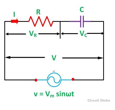
A circuit that contains pure resistance R ohms connected in serial with a pure capacitor of capacitance C farads is known as RC Series Circuit. A sinusoidal voltage is practical and current I flows through the resistance (R) and the capacitance (C) of the circuit.
The RC Series circuit is shown in the figure below:
 Where,
- VR – voltage beyond the resistance R
- VC – voltage across capacitor C
- Five – total voltage across the RC Series excursion
Contents:
- Phasor Diagram of RC Series Circuit
- Steps to draw a Phasor Diagram
- Phase bending
- Power in RC Series Circuit
- Waveform and Power Curve of the RC Series Circuit
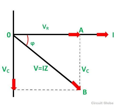
Phasor Diagram of RC Serial Excursion
The phasor diagram of the RC series excursion is shown below:
Steps to depict a Phasor Diagram
The post-obit steps are used to depict the phasor diagram of RC Series circuit
- Take the current I (r.thousand.south value) equally a reference vector
- Voltage drop in resistance VR = IR is taken in phase with the current vector
- Voltage drop in capacitive reactance VC = IXC is fatigued ninety degrees behind the current vector, every bit current leads voltage by ninety degrees (in the pure capacitive circuit)
- The vector sum of the 2 voltage drops is equal to the practical voltage V (r.m.s value).
At present,
VR = IR and VC = 9C
Where XC = I/2πfC
In right triangle OAB,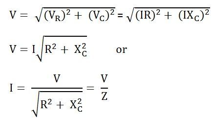
Where,
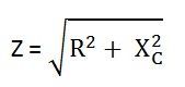
Z is the full opposition offered to the flow of alternating current by an RC series circuit and is chosen impedance of the circuit. It is measured in ohms (Ω).
Stage angle
From the phasor diagram shown higher up, it is clear that the current in the excursion leads the applied voltage by an angle ϕ and this angle is called the stage angle.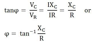
Power in RC Series Circuit
If the alternating voltage applied beyond the circuit is given past the equation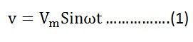
Then,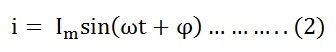
Therefore, the instantaneous power is given by p = vi
Putting the value of five and i from the equation (i) and (two) in p = 6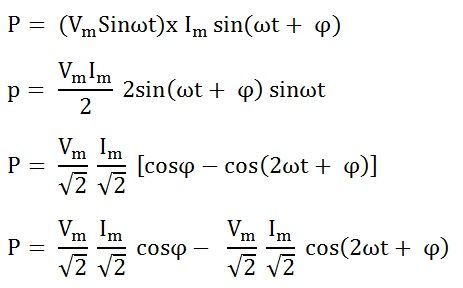
The average ability consumed in the circuit over a complete cycle is given by: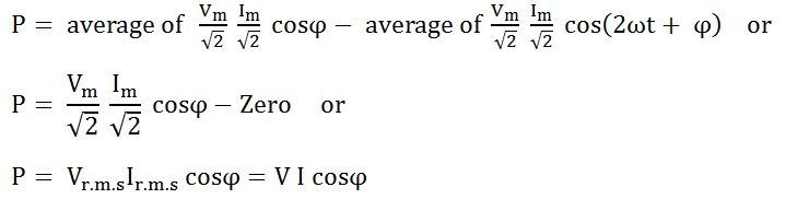
Where cosϕ is called the power factor of the circuit.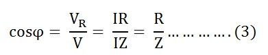
Putting the value of Five and cosϕ from the equation (3) the value of ability volition be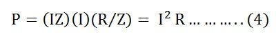
From the equation (4) information technology is clear that the ability is actually consumed past the resistance just and the capacitor does not consume any power in the circuit.
Waveform and Power Curve of the RC Series Circuit
The waveform and ability bend of the RC circuit is shown beneath:
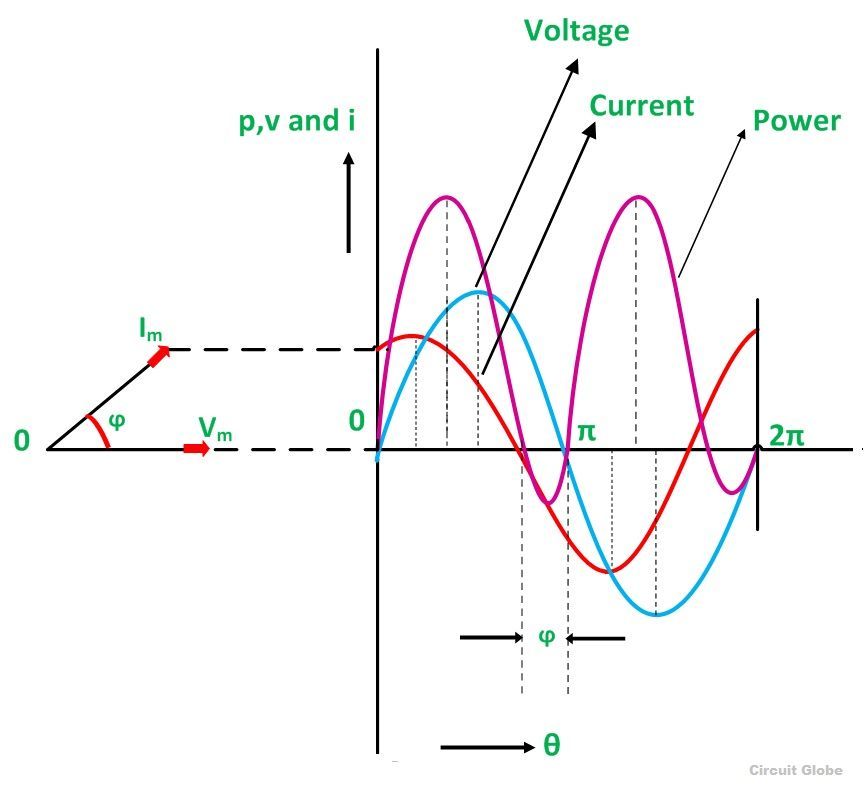 The diverse points on the power curve are obtained from the product of the instantaneous value of voltage and current.
The ability is negative between the angle (180° – ϕ) and 180° and between (360° -ϕ) and 360° and in the remainder of the bike, the power is positive. Since the area nether the positive loops is greater than that under the negative loops, therefore the internet power over a complete wheel is positive.

How To Draw Phasor Diagram With Voltage And Current,
Source: https://circuitglobe.com/what-is-rc-series-circuit.html
Posted by: duncanboyaceing.blogspot.com
0 Response to "How To Draw Phasor Diagram With Voltage And Current"
Post a Comment